LTE is a standard for wireless communication and LTE Advanced / LTE Advanced Pro (Cat 6 to Cat 19) is a high-speed version of LTE, sometimes marketed as LTE+, 4G+, 4GX,4.5G or 4G LTE Ultra. LTE support varies from country to country, and the speed may vary depending on user location and how fast they’re traveling.
LTE (Cat 1~5)
LTE has been introduced in 2012 in order to provide high data rate mobile broadband connection.
It has been introduced to provide 10 times faster data rate compared to 3G.
LTE provides 100 Mbps.
LTE has been specified in 3GPP Rel.8.
LTE supports carrier bandwidth of 20 MHz.
LTE Advanced (Cat 6~16)
LTE Advanced is an enhancement to LTE with data rate increase to the factor of 10.
It supports carrier aggregation and higher order MIMO techniques.
It supports the data rate of 1 Gbps in downlink (From eNB to UE) and 500 Mbps in uplink direction (From UE to eNB).
LTE Advanced Pro (Cat 17~19)
It is enhanced version of LTE Advanced to support higher data rate beyond 3 Gbps.
It supports increased Bandwidth, increased efficiency and improved latency.
It makes use of both licensed (400 MHz to 3.8 GHz) and unlicensed (5GHz) spectrum to support up to 32 carriers of 20MHz each.
It is backward compatible with existing LTE and LTE Advanced devices.
It makes use of spectrum more efficiently by increasing number of antenna paths as well as multi beam approach. It serves single radio cell with 16 to 64 antenna paths.
It grows network capacity to about 200% without any additional spectrum or base stations.
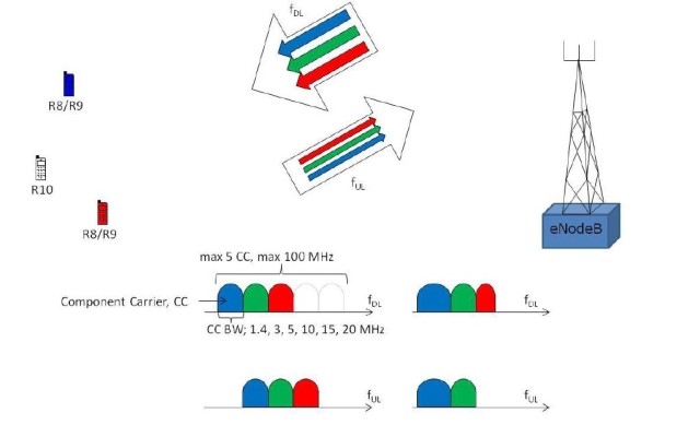
In this article I would like to explain the concept or the technology carrier aggregation in connection with LTE. Carrier aggregation, in short CA , is an important component of the 3GPP release 10, and thus of LTE-Advanced ( LTE-A ), which was specified in 3GPP Release 10. LTE-A consists of several components, including CA, for example 8 × 8 MIMO, and LTE UE categories 6, 7 and 8.
In addition to a higher speed (up to about 1.2 gigabits per second downstream in LTE cat. 8 UE) compared to normal LTE, improved data rates on the cell edge are also a plus for LTE-A. However, in spite of various optimizations, one will need more frequency spectrum in the future in order to be able to further increase the data rates and meet the increase in global traffic – the peak data rates of LTE-A can only be achieved if up to 100 MHz are bundled. And this is where Carrier Aggregation is used.
Problem: Frequency spectrum is a scarce resource
The topic affects almost all mobile network operators in the world: they do not have enough coherent frequency spectrum to easily offer the high data rates of LTE-A. In Germany, for example, there is only 20 MHz bandwidth available in the frequency range around 800 MHz – paired in 4 blocks, ie 10 MHz for the downlink and 10 MHz for the uplink. In the configuration currently in use (2 × 2 MIMO, LTE UE Cat. 3), a maximum of 75 MBit/s can be reached in the downstream, although not much more than 60 MBit/s is possible.
Fortunately, the providers in Germany have enough spectrum to be able to connect at least LTE cat. 4 with up to 150 MBit/s without much effort, at least in the frequency ranges around 1800 MHz and 2600 MHz. It is only more difficult if higher speeds are desired. In other countries, such as South Korea, for example, there is already this problem, where carrier aggregation is used. Before I get to the details of this technology, first a short video from the company Qualcomm, which explains the functionality in a quite appealing way:
Carrier aggregation: bundling of different frequency
Blocks with CA, the network operators are able to bundle different frequency blocks into a large block for the first time. After 3GPP release 10, the upper limit is at 100 MHz, although a later expansion is of course not excluded. In the medium term, however, it is likely to be a bundling of 40 to 60 MHz.
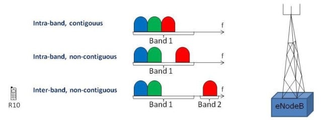
There are three different modes for channel bundling, whereby only the following carriers can be combined: 1.4 / 3/5/10/15/20 Megahertz. How and in what way the combination takes place is left to the network operator, but maximum of 5 carriers can be bundled:
Intra band, contiguous:this is the simplest CA method. Two or more frequency blocks are clustered, contiguous and within a frequency range (Intra band). So, for example, 2x 10 MHz in band 3 (frequency range around 1800 MHz). The terminal does not need any great hardware changes because it perceives the aggregated channel as a large channel and therefore requires only one transceiver (transceiver).
Intra band, non-contiguous: in this method, two or more carriers are bundled, these frequency blocks being not adjacent but lying in the same frequency range. On the end of the terminal, two or more transceivers are now required to use the aggregated band.
Inter-band, non-contiguous: this CA method is likely to be the most widely used in the future as it is most likely to be true for network operators. In this case, frequency blocks from different frequency ranges can be bundled in order to create the largest possible frequency block. A possible scenario would be, for example, the combination of spectrum from band 20 (around 800 MHz) with spectrum from band 3 (1800 MHz). As you can imagine, several transceivers and further optimizations are necessary in the terminal, which can have a noticeable effect on the energy consumption.
Different ranges of individual carriers and downwards compatibility
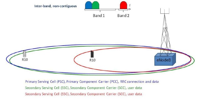
Especially in the case of carrier aggregation using inter-band, non-contiguous, it is inevitable that there will be differences in the size of the individual cells. Thus, with a terminal with CA support close to an LTE transmitter (eNodeB), very high speeds will be achieved as the terminal can use a lot of bundled spectrum. A few kilometers from the transmitter is possibly only LTE800 receivable and CA brings no more advantage.
As can be seen in the above, there is always a Primary Serving Cell, or PCC, a “main cell”, which ensures the supply. The other cells (SCC) serve merely as a support for user data, in other words to increase the bandwidth. Depending on the terminal, the PCC can be different, depending on various factors, for example the respective energy consumption in the terminal. This, of course, requires a lot of optimization both in the network planning and in the manufacturers of the modems for mobile devices.
Of course, CA and thus also LTE-A is down-compatible with “conventional” LTE. Old and currently available terminals are therefore still usable in the future. Nevertheless, if you want to use the higher bandwidths or carrier aggregation, you obviously need a new terminal. Here, again, the LTE UE category has to be considered, CA alone is not enough to achieve speeds in the gigabit range.